QuadRF: Seeing Wi‑Fi and Tracking Drones with a Raspberry Pi Phased Array
 by ahsan
July 10, 2026
6 min read
by ahsan
July 10, 2026
6 min read
The day “Wi‑Fi through the wall” stopped sounding like sci‑fi
Imagine this: you’re in your home office, and a video call keeps stuttering. The router is in the living room, the signal bars are technically “fine,” but performance feels haunted. Then you stumble across a demo claiming a tiny phased‑array radio can spot drones overhead—and even visualize Wi‑Fi signals beyond walls.
That’s the kind of claim that usually turns into either hype or fear. This time, though, it’s worth getting curious about the engineering—because QuadRF is a real, buildable system designed to “see” radio waves by turning directional signal processing into something you can watch.
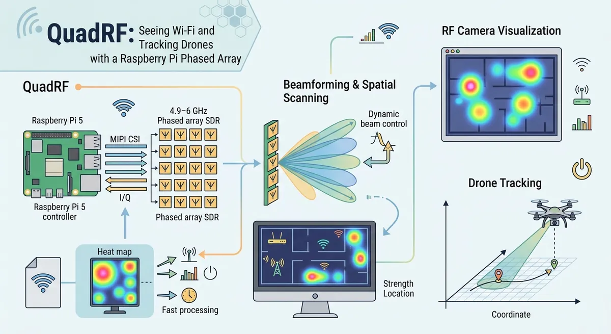
Can a small phased array actually see Wi‑Fi through walls? QuadRF’s core idea is straightforward: use software-defined radio (SDR) to digitize signals, then use beamforming (more on that soon) to steer sensitivity toward where the signal seems to come from—creating a real-time “RF camera” effect in the 4.9–6 GHz range. (moonrf.com)
What QuadRF is, in plain language
At a high level, QuadRF is a modular phased-array SDR tile built around a Raspberry Pi 5 plus an FPGA (field-programmable gate array). The FPGA is a chip you can configure with custom digital logic, which is useful when you need fast signal processing and precise timing.
QuadRF’s tile includes four coherent full‑duplex RF chains and a 4-antenna phased array, meaning it can transmit and receive while keeping channel timing aligned. (moonrf.com)
Here’s the key: QuadRF doesn’t rely on “guessing Wi‑Fi.” Instead, it samples the radio waveform as I/Q data—two numbers per sample that represent the signal’s in‑phase and quadrature components—then combines those I/Q streams with controlled phase shifts to form a directional view.
That combination step is where the “vision” comes from.
The RF camera effect: SDR + beamforming
Let’s unpack the two big ideas.
Software-defined radio (SDR)
Software-defined radio (SDR) means the radio’s “thinking” happens in software rather than fixed-purpose hardware. In practice, an SDR captures radio energy at a chosen frequency and converts it into a digital stream of numbers.
QuadRF supports streaming I/Q in formats used by SDR frameworks like SoapySDR, and by default it can operate in a beamforming mode where multiple antennas contribute to a single combined I/Q stream. (moonrf.com)
Beamforming
Beamforming is a technique where you shift each antenna’s signal by a carefully chosen phase (and sometimes amplitude), then sum them. If a signal arrives from the “target” direction, the phases line up and the sum gets stronger. If it arrives from elsewhere, the phases don’t align and the sum becomes weaker.
With four antennas, the number of “steering angles” isn’t infinite, but it’s enough to create a useful spatial picture—especially when the software sweeps or tracks the strongest source.
The QuadRF documentation describes automatic beamforming that can steer toward what it is receiving to maximize signal strength, which helps explain why a drone’s transmissions can show up as distinct moving blobs in a visualization. (moonrf.com)
So what does “through walls” really mean?
Radio waves don’t respect the drywall between you and the router. At 5 GHz (Wi‑Fi’s common “Channel 100-ish” neighborhood), signals can weaken, reflect, and diffract around obstacles.
So the system isn’t “seeing through walls” like an X‑ray. It’s doing something more physical: it’s detecting what survives the path(s) through the building, then using spatial processing to infer the most likely direction components.
That’s the difference between a magic claim and a measurable one.
How QuadRF streams I/Q so fast (and why MIPI is the secret sauce)
A big practical problem in SDR is bandwidth. If you digitize a wide chunk of spectrum and want near real-time visualization, you must move I/Q samples from the RF front end to the processor without dropping samples.
QuadRF’s clever part is its use of the Raspberry Pi 5’s MIPI connectors through special hardware wiring:
- The RF board interfaces to the Pi 5 using two flexible flat cables (FFC) carrying I/Q data at 5.6 Gbps. (moonrf.com)
- RF transmit uses the Pi 5’s DSI (display) connector, while receive uses CSI‑2 (camera). Both can operate in parallel for full-duplex operation. (moonrf.com)
- The documentation calls out that MIPI can handle >5 Gbps, enabling low-latency full‑duplex transfer through the Pi’s RP1 chip. (moonrf.com)
Why this matters: RP1 and MIPI
On Raspberry Pi 5, RP1 is an I/O controller that manages peripheral interfaces and includes dedicated MIPI support for both DSI and CSI‑2. (raspberrypi.com)
In SDR terms, this means the “RF-to-processor data pipe” is built from an interface the Pi designers already optimized for high-rate streaming, rather than overloading slower or more fragile paths.
QuadRF’s docs also mention the system can sustain hundreds of MSPS (million samples per second) without hiccups or sample loss—exactly what you need for a responsive RF visualization pipeline. (moonrf.com)
Chasing drones: what you’re actually observing
Drones (and many video links) produce radio transmissions that are spatially localized in both time and direction.
When a QuadRF tile tracks the strongest source with beamforming, the resulting visualization behaves like a moving target in a radar-like display:
- As the drone comes into alignment with the phased array’s “best” direction, the beamformed sum rises.
- As it moves away, the phase relationship changes, and the strength drops unless steering updates.
In the QuadRF project materials, the drone use case is described as a central “spatial domain” demo, with additional software targeting real-time decoding of certain analog video transmissions. (moonrf.com)
This is also where practical limitations show up. If you’re holding the unit and changing alignment, the effective beam direction can drift, requiring more gain or recalibration. That’s not a bug—it’s a reminder that beamforming is a geometry problem, and geometry depends on where the antennas physically point.
A beginner-friendly mental model: phase is the dial
Beamforming can feel abstract until you translate it into a simple mental image.
Think of each antenna as a microphone that captures the same sound—but with a slightly different “arrival time” depending on direction. Time differences become phase differences for a given frequency.
To steer a beam, you apply compensating phase shifts so that a signal from the direction you care about adds up constructively.
Here’s a tiny conceptual snippet showing what “apply phase and sum” looks like in the complex-number world SDR uses.
import numpy as np

# Complex I/Q samples for one antenna (shape: N samples)
# In real SDR code, these come from the RF digitization step.
X0 = np.array([...], dtype=np.complex64)
X1 = np.array([...], dtype=np.complex64)
X2 = np.array([...], dtype=np.complex64)
X3 = np.array([...], dtype=np.complex64)

# Precomputed beamforming weights (one per antenna)
# Each weight is a complex number: magnitude controls gain, angle controls phase.
weights = [w0, w1, w2, w3]

beam = weights[0]*X0 + weights[1]*X1 + weights[2]*X2 + weights[3]*X3

# The “visualization power” often relates to magnitude squared
power = np.abs(beam)**2
The exact math depends on how the software estimates steering angles and how it chooses weights, but the structure stays the same: phase-correct each antenna’s stream, sum, then measure power (or extract features) for visualization.
Why the open-source ecosystem matters
QuadRF’s documentation emphasizes using established SDR interfaces like SoapySDR and providing mechanisms to run processing either locally on the Pi or on a client machine over the network. (moonrf.com)
That’s important because “RF visualization” isn’t one program—it’s an ecosystem of decoders, analyzers, and custom processing experiments.
When a platform lowers the barrier to building RF spatial experiments, it accelerates learning in the same way that open learning tools accelerated programming. The ethical lesson is similar: power without understanding is dangerous, but transparent tools support safer, more responsible experimentation.
Conclusion: what QuadRF teaches about modern RF
QuadRF is compelling not because it turns walls into portals, but because it makes a hard problem—spatial RF sensing—more approachable with real hardware and fast I/Q streaming.
By combining SDR digitization, phased-array beamforming, and a high-throughput MIPI-based data path built around the Pi 5’s RP1 architecture, it can visualize signals in a meaningful spatial way over 4.9–6 GHz. (moonrf.com)
Once you see that pipeline end-to-end, the “drone tracking” and “Wi‑Fi through walls” story stops being spooky and becomes engineering: geometry, phase, bandwidth, and software that turns radio waves into something your eyes can interpret.
Comments (0)
No comments yet. Be the first to respond!
Leave a Comment
Your comment will be visible after review.